Articles
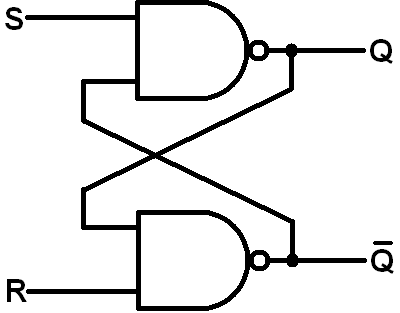
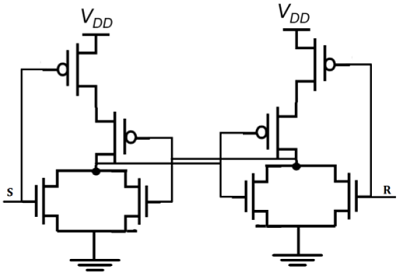
S R Latch Notes
So S and R will invert. But slave remains inactive all this time since clock is 1. As soon as clock becomes 0, slave becomes active and master becomes inactive. So slave will also toggle. These changed outputs are returned through feedback to the master, but master does not respond to them because clock is now 0 and master is inactive. The difference is that the JK Flip Flop does not the invalid input states of the RS Latch (when S and R are both 1). The JK Flip Flop name has been kept on the inventor name of the circuit known as Jack Kilby. The basic symbol of the JK Flip Flop is shown below.
I am thinking of some kind of fault circuit, but I would like to consult you about whether it is useful or not.
As an example, consider a kind of circuit, and this circuit contains fault detection circuits in various parts. For example; over temperature, humidity, over current / voltage etc. I plan to apply it to the inputs of an S / R Latch IC when any malfunction like these is detected. The outputs of the Latch IC will be interconnected with the OR gate. Thus, in case of any malfunction, whatever malfunction occurs, the S / R latch output will be 1 and the output of the OR gate will also be 1. The output of the OR gate will also be connected to the interrupt pin of a microcontroller, and it will stop the operation of the system safely. The reset of the S / R latch will be provided by the user pressing the button on the card or by an external controller. In this way, the output of the OR gate will be 0 and the microcontroller will control the system again.
Do you think this idea is useful? What would you suggest me?
front 1 A D flip-flop utilizing a PGT clock is in the CLEAR state. Which of the following input actions will cause it to change states? | back 1 |
front 2 Which statement BEST describes the operation of a negative-edge-triggered D flip-flop? | back 2 The logic level at the D input is transferred to Q on NGT of CLK. |
front 3 The circuit that is primarily responsible for certain flip-flops to be designated as edge-triggered is the: | back 3 |
front 4 As a general rule for stable flip-flop triggering, the clock pulse rise and fall times must be: | back 4 |
front 5 Determine the output frequency for a frequency division circuit that contains 12 flip-flops with an input clock frequency of 20.48 MHz. | back 5 |
front 6 An active-HIGH input S-R latch has a 1 on the S input and a 0 on the R input. What state is the latch in? | back 6 |
front 7 | back 7 |
front 8 | back 8 Q output follows the input D when the enable is HIGH. |

front 9 | back 9 |
front 10 What is the significance of the J and K terminals on the J-K flip-flop? | back 10 The letters were chosen in honor of Jack Kilby, the inventory of the integrated circuit. |
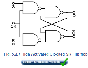
front 11 If both inputs of an S-R flip-flop are low, what will happen when the clock goes HIGH? | back 11 |
front 12 Which of the following best describes the action of pulse-triggered FF's? | back 12 The data is entered on the leading edge of the clock, and transferred out on the trailing edge of the clock. |
front 13 Which of the following is not generally associated with flip-flops? | back 13 |
front 14 | back 14 |
front 15 A gated S-R latch and its associated waveforms are shown in Figure 5-1. What, if anything, is wrong and what could be causing the problem? | back 15 The output is always low; the circuit is defective. |
front 16 A push-button switch is used to input data to a register. The output of the register is erratic. What could be causing the problem? | back 16 |
front 17 The circuit in Figure 5-2 fails to function; the inputs are checked with a logic probe and the following indications are obtained: CLK, J1, J2, J3, K1, K2, and K3 are pulsing. Q and clr.gif are HIGH. q.gif and PRE are LOW. What could be causing the problem? | back 17 |
front 18 A positive edge-triggered J-K flip-flop is used to produce a two-phase clock. However, when the circuit is operated it produces erratic results. Close examination with a scope reveals the presence of glitches. What causes the glitches, and how might the problem be corrected? | back 18 A race condition exists between the clock and the outputs of the flip-flop feeding the AND gate; replace the flip-flop with a negative edge-triggered J-K Flip-Flop. |
front 19 Four positive edge-triggered D flip-flops are used to store a 4-bit binary number as shown in Figure 5-3. Determine if the circuit is functioning properly, and if not, what might be wrong. | back 19 |
front 20 A 555 timer is connected for astable operation as shown in Figure 5-4 along with the output waveform. It is determined that the duty cycle should be 0.5. What steps need to be taken to correct the duty cycle, while maintaining the same output frequency? | back 20 |
front 21 In VHDL, in which declaration section is a COMPONENT declared? | back 21 |
front 22 In VHDL, how many inputs will a primitive JK flip-flop have? | back 22 |
front 23 | back 23 |
front 24 In VHDL, how is each instance of a component addressed? | back 24 A name followed by a colon and the name of the library primitive |
Sr Latch Notes Book


Sr Latch Notes Definition
front 25 | back 25 |
front 26 LPMs do not attempt to simulate specific standard ICs. In which Quartus library would these modules be found? | back 26 |